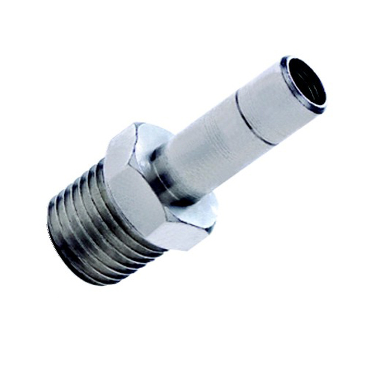
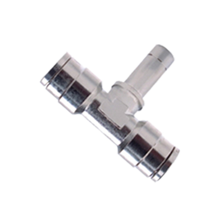
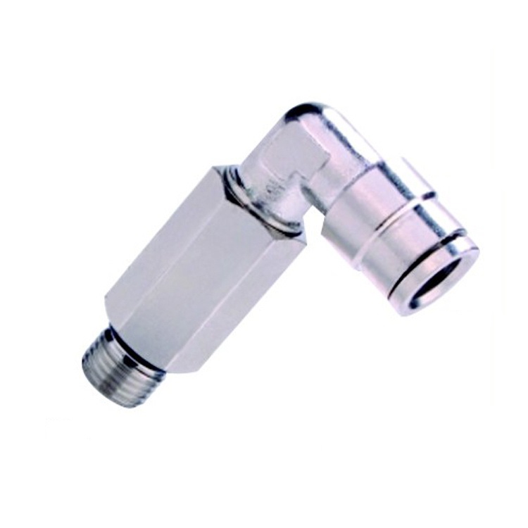
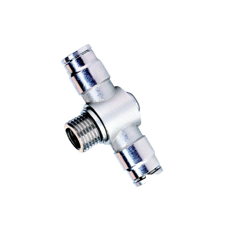
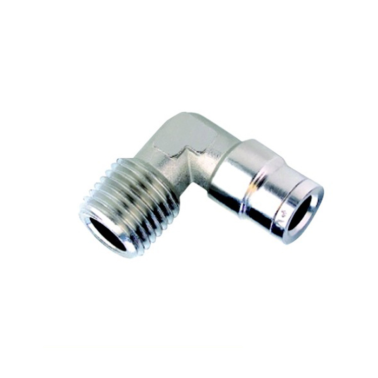
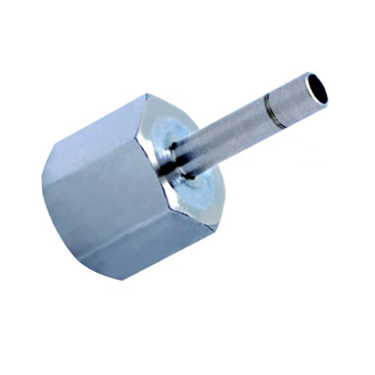
BJM Stem To Male Tube to Pipe Brass One Touch Fittings
| Mod. | G | D | H | T | L | SW | Weight (g) |
| BJM-M04-M5 | 4 | M5 | 4 | 16.5 | 24.5 | 8 | 3 |
| BJM-M04-G02 | 4 | Gl/8 | 5.5 | 16.5 | 27.8 | 12 | 10 |
| BJM-M05-G2 | 5 | Gl/8 | 5.5 | 18 | 29.3 | 12 | 9 |
| BJM-M05-G4 | 5 | Gl/4 | 7 | 18 | 31 | 14 | 11 |
| BJM-M06-G2 | 6 | Gl/8 | 5.5 | 18 | 29.3 | 12 | 10 |
| BJM-M06-G4 | 6 | Gl/4 | 7 | 18 | 31 | 14 | 12 |
| BJM-M08-G2 | 8 | Gl/8 | 5.5 | 20.5 | 31.8 | 12 | 12 |
| BJM-M08-G4 | 8 | Gl/4 | 7 | 20.5 | 35.5 | 14 | 13 |
| BJM-M10-G4 | 10 | Gl/4 | 7 | 23 | 36 | 14 | 16 |
| BJM-M10-G6 | 10 | G3/8 | 8 | 23 | 37.3 | 19 | 25 |
| BJM-M12-G6 | 12 | G3/8 | 8 | 24 | 38.3 | 19 | 25 |
| BJM-M14-G8 | 14 | Gl/2 | 9 | 28 | 44 | 22 | 59 |
Interchangeability for reference
Parker : 68PLMSP-4M-M5 68PLMSP-4M-2G 68PLMSP-4M-4G 68PLMSP-6M-2G 68PLMSP-6M-4G 68PLMSP-8M-2G 68PLMSP-8M-4G 68PLMSP-8M-6G 68PLMSP-10M-4G 68PLMSP-10M-6G 68PLMSP-10M-8G 68PLMSP-12M-6G 68PLMSP-12M-8G 68PLMSP-14M-8G
Eaton/WeatherHead :1180x4Mx2PP 1180x5Mx2PP 1180x6Mx2PP 1180x6Mx4PP 1180x8Mx2PP 1180x8Mx4PP 1180x10Mx4PP 1180x10Mx6PP 1180x12Mx6PP
Midland :
Camozzi :
attention please :Quotations and delivery of non-stock items supplied on request. Configurations and dimen sions subject to change without notice.
Metal/Brass Push-In Fittings
Features
- Simply to install & uninstall with no tools.
- Stainless steel tube locking mechanism.
- Thread sealant on taper threads, O-ring face seal on G threads.
- NBR as the standard sealing material,other materials are available upon request.
- Nick plated is standard for bass surface treatment, ensure anti-corrosion and anti-contamination.
- Reuseable-Can be assembled and disassembled repeatedly. (recommend to cut the surface-damaged part of tube)
- Thread: BSPP, BSPT, NPT (Please contact us for other styles)
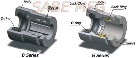
Construction
Specification
| O-Ring Seal | NBR (other materials are available upon request) |
| Gripping Mechanism | Stainless Steel |
| Temperature Range | 32° F to 176°F (higher temperature are possible with special O-rings) |
| Pressure Max | 230 PSI (mainly limited by tube’s enduring) |
| Vacuum Duty | 29.5 Inch Hg |
| Media | Compressed Air |
Note: These meant only as a guide to aid in design. Field testing should be performed to find the actual values for your application.
Installation Instructions
 |
 |
| Figure 1 | Figure 2 |
To connect tube (see figure 1)
- Cut tubing squarely–maximum of 15° angle allowable.Use of tube cutter (PTC) is recommended.
- Check that port or mating part is clean and free of debris.
- Insert tube into fitting until it bottoms.Push twice to verify that tubing is inserted past collet & O-Ring.
- Pull on tubing to verify it is fully inserted.
To disconnect tube (see figure 2)
- Simply press release button, hold against body, and pull tubing out of fitting.

